|
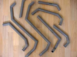
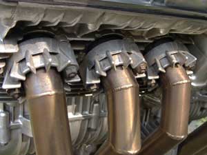
Ingredients: angular and stainless steel. |
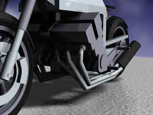
In the first version you see three exhaust pipes ending in a triangular carbon muffler. Lots of puzzling rendered a seperate collector obsolete.
A slip-on system with springs make it easy to disassemble the muffler.
Like claws.
Between September 2000 and June 2002 the CBX INOX was drastically rebuilt.
![]()
The exhaust has been renewed totally.
![]()
Why a new exhaust? The first one (a six-into-two) did great. The big peg brackets and both mufflers however hid the view on the long swingarm; they weakened the desired dragracer-concept.
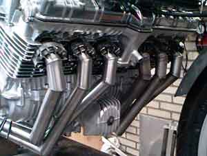
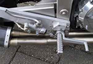
By placing the new stainless steel mufflers on both sides of the engine, the peg brackets could be removed. You have a clear view on the swingarm and the rear wheel appears to be detached from the bike. And that's exactly what I intended.
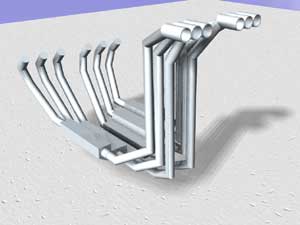
So october 2000 I had to go back to the 3D-program Form*Z once more. The first concept was six-into-six seatpipes.
So october 2000 I had to go back to the 3D-program Form*Z once more. The first concept was six-into-six seatpipes.

That looked quite good from behind, but there were two big disadvantages: the 'knot-of-curves' between the monoshock and the rear wheel did not look very professional, even a bit cluttered. And where would I place the cameras?
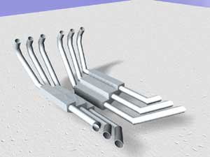
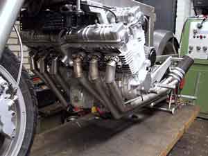
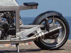
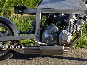
The final concept was plain and simple: six pipes along the bottom of the bike, in line with the engine.
The ends pointed up like dragracers have them too.
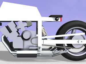
The exhaust intensifies the longitude of the bike; the rear wheel is totally free.
I used PVC tube to make prototypes. PVC is not rigid enough for accurate experiments but it's useful to get a good picture of the bike's looks.
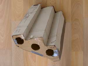
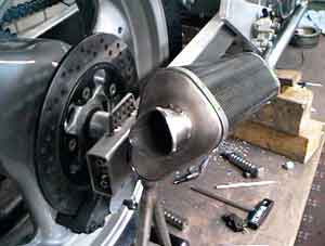
The muffler too was first made out of cardboard to determine the exact size, position and mount points on the engine.
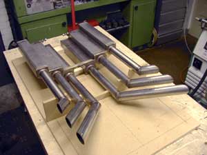
Preceeding the welding everything was positioned exactly in a wooden mould.
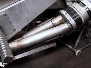
An exhaust with its own looks ...
... and yes, its very own sound ;-)
... and yes, its very own sound ;-)
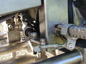
The footpegs now hinge to the back diagonally. The rear master cylinder and the stoplight switch are operated by a T-form lever which hinges around an axle at the bottom of the frame.
July until November 2003 I initiated 'Stage III': radical and less radical changes combined with necessary maintenance.
I did some polishing on the exhaust pipes and replaced the bolts ... by stainless ones, of course.
Aim at the picture to view the result.
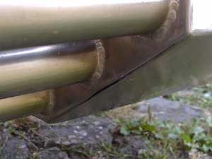
Due to extreme temerature changes in the exhaust system the silencer tore. Willy Naves repaired it.
Aim at the picture to view the welded silencer.